This is a small robot I hooked up to my PC and I added some TTS (Text-To-Speech). I think this is around 2007, so it’s pretty old footage. For anyone that recognizes it, this is the same J.A.R.V.I.S. voice I use for my house and during my CodeMash talks.
Same robot but doing some computer vision. I ended up using blue because of the low light and the cheap webcam tended to make everything green & red.
Feynman Series – Navigating The Sidewalk
Little bit more coding than I thought to make this work. This is a smaller version of the Feynman Series robot, the Feynman Jr. series. I ended up using some different motors as well, two NPC-2212 with 6″ wheels. Turns out it was a very rough ride, eventually the webcam servo mount broke because of the shock.
This is a continued post about my robots as I prepare to archive and rebuild ScottsBots.Com.
Feynman MK1 – 2002
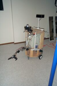
The “Feynman” name for my robots actually comes from the names of the computers in my house, this computer housed in wood below was called Feynman, and I happened to turn it into a robot.
This robot came equipped with a robot arm, sonar, a compass, and a webcam. The chassis was made from plywood and PVC. The motors were Black & Decker cordless drills. I powered the drills via speed controls from robot control cars. It had speakers and could “talk” using primitive text to speech. It was still powered via 110 VAC.
The computer itself was an AMD K6-2 500MHz, running Windows 2000 and Visual Basic 6. I programmed and tested it using VNC. I used a Basic Stamp 2 to get sensor readings from the sonar, compass and infrared sensors. I used the Scott Edwards Mini-SSC to control PWM channels on the speed controller connected to the drill motors.
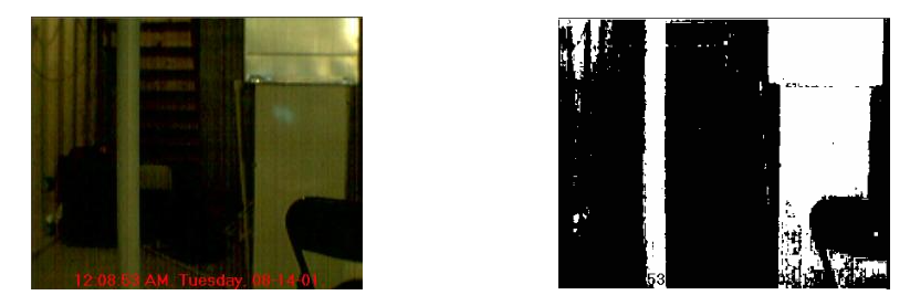
Computer Vision Tinkering
From the image above, I also started to tinker with computer vision. This was a simple VB6 thresholding program, where i looped through all the pixels and if they were below a certain number I changed them to zero (black) and if they were above it, I changed the pixel to 255 (white).
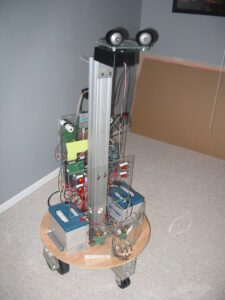
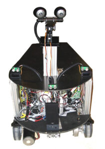
Feynman MK3 – 2003
This version contained a lot of upgrades. I still had a plywood base but I used 80/20 Aluminum Extrusion for the chassis and I used 2 33AH Batteries for power. I upgraded the drive motors to use two windshield wiper motors from an F-150. I upgraded the speed controls to two Victor 883 from IFI Robotics @$150 each. I upgraded the webcams to Two Pyro 1394 Firewire webcams.
The computer changed to a lower powered version. VIA EPIA M10000 Mini-ITX with 259 MB of ram and a 20GB HDD. It had Wi-Fi and all the software to program and run it was 100% Java.
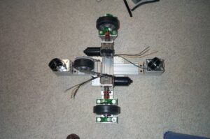
This is a picture of the base of the robot. The drive system used coupling nuts connected directly to the shaft of the wiper motors and the wheels. This wasn’t very efficient and the motors themselves didn’t prove to be that reliable. Another thing I didn’t do well with this design was account for the spacing of the caster wheels. They were a little above the drive wheel and movement of this robot was a little jarring as it would rock back and forth when starting and stopping. This rocking eventually led a really difficult time doing computer vision with the two cameras, ultimately i needed a better solution.
This design and software to run it is outlined completely in the book. Additional upgrades include PVC from McMaster Carr. Two new NPC-41250 Motors from National Power Chair. 3 SRF-4 Devantech Sonar Sensors. I also removed the front caster made it a little backwards heavy so it rested on the batteries. This created a much more stable platform for moving around doing navigation.
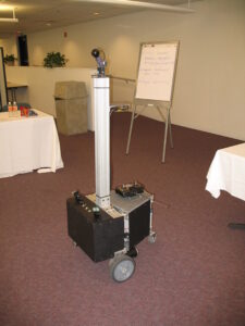
Feynman MK6 – 2005
Once I wrote the book I started getting invited to speak at local user groups and conferences about Java and Robots.
I created a switch so that I could remote control the robot as I would drive it places. This is the robot at some location in town, it could even be a conference. This robot is mostly the same as Feynman 5, just a little taller with a single webcam.
I think this was the first version of my robot I took to CodeMash. as speaker.
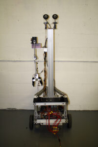
Feynman MK7 – 2006
This is the final version of the robot.
Most of this robot remains unchanged to this day. I removed and upgraded the computer a few times, eventually switching to a Raspberry Pi, but ultimately the robot proved too difficult to transport. It weighted about 200 pounds and required 2-3 people to load into the truck to transport to conferences and meet-ups. Currently this robot sits in the garage unused. 🙁
I thought I’d put a post together summarizing some of my robots as I prepare to archive and rebuild ScottsBots.Com.
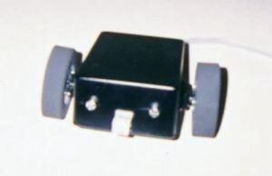
TetherBot – 1999
I built this robot in 1999. I hacked two hobby servers (Futaba 3003) to make it move and built my own sensors with some parts from Radio Shack. To move this robot I connected an ethernet cable to the parallel port on my Windows 98 Machine.
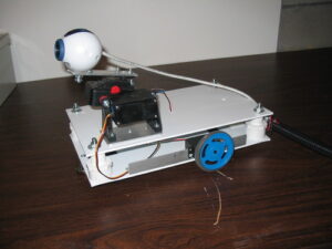
Baby Joe – 2001
This was my second and third robot. I reused the hacked servo motors from TetherBot, but this time I used a Basic Stamp microcontroller to control the IR sensors and send PWM signals to the servo motors. I also used Aluminum and plexiglass as construction materials.
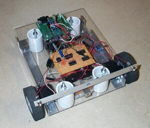
Rovey – 2002
I started to experiment with different chassis materials (this time PVC). Also because I had more servos (pan/tilt) webcam and 2 drive servos (same ones) I upgraded the controller from a Basic Stamp 2 to a Scott Edwards Mini-SSC. This device allowed me to send commands to the servos with 3 bytes (255, servo(0-7), position (0-255). So (255,0,127) would send a stop/neutral pulse to servo connected to the 0 pin. (255,0,0) would send full clockwise pulse to the servo on pin 0. (255,0,255) would send a full counter clockwise pulse to the servo on pin 0. This is a great little board and one I use to this day on some of my new robots.
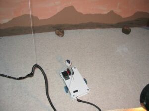
I created this robot for a talk at COSI. The idea was that students could login and control the robot from a web browser. The idea of the talk was to connect with Mars Pathfinder robot which at the time was discovering it’s way around Mars. The photo isn’t great I tried to create a Martian landscape and added rocks for the robot to explore. The robot was tethered so it could have continuous power, but to prevent the robot from getting tangled I connected the robot wires to a string hung from the ceiling.
In early December during the build of the Mark3 suit I had a catastrophic failure of my CNC Z-Axis limit switch. (See Below).
Because of this the machine was unable to home, and without being able to home, I couldn’t cut anything. I was unable to get it fixed with new parts until the week of Christmas and didn’t want to spend my entire holiday catching up trying to get it built.
I will post about the Mark 3 on my YouTube Channel “Almost Iron Man“.
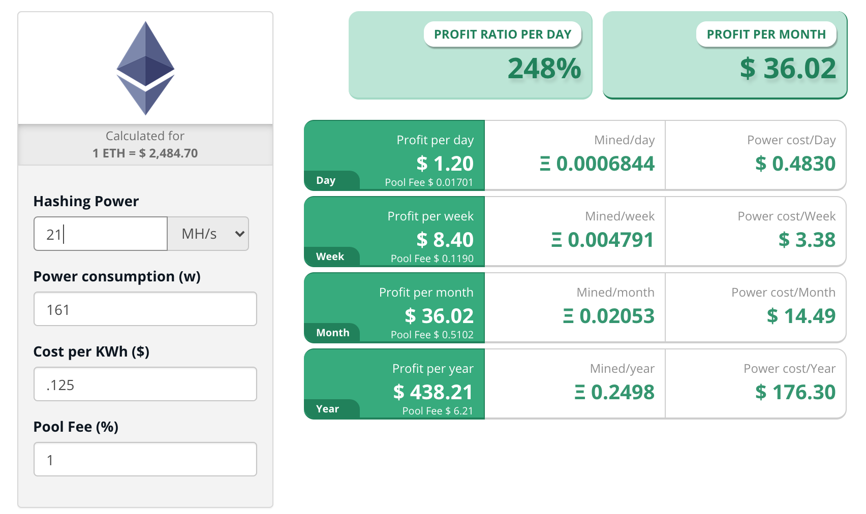
So this week-end I did an experiment with Ethereum Mining. The first thing I did was use a calculator. Here’s one from CryptoCompare.com.
CryotoCompare.com
Now according to this calculator, I should make around $36 bucks a month for my Nvidia GTX 1060 Card. Well, I did an experiment and after 28 hours I made $1.10. This comes out to about $0.04/hour or $0.94/day, but I’m actually paying $0.49 in electricity cost. So the net is $0.45/day or $13.71 per month. This makes the calculator wrong by about 263%. This link above has net profit at $1.20/day. So the hash rate was a lot lower than stated both on miner and on other estimates for this card.
I found this when looking for media from my original Exo-Skeleton talk. Sadly nobody thought of recording it while doing the talk, we were all too busy hoping I wouldn’t fall over.